ECE 110/Equipment/Keysight EDU33211A
Contents
Introduction
The waveform generator will be used to generate time-varying signals, generally voltages. This document specifically relates to the Keysight EDU33211A Waveform generator.
Generating Waveforms

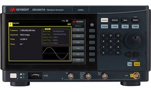
The Keysight EDU33211A waveform generator is used to provide voltages that vary with time. It has four primary waveforms: sine, square, ramp and pulse. There are three parameters that can be varied for each waveform:
- Frequency (0-20 MHz)
- Amplitude (Peak-to-Peak [Pk-Pk] 0-10 V)
- DC offset
To set any of these parameters, press the button labeled with the feature you wish to modify. The present setting of this feature will appear. Notice that one of the digits is highlighted. Turning the dial (located on the top right of the front panel) will change the value of this digit. You can change which digit is highlighted by pressing the left or right arrow keys (located above the output jack). It is also possible to enter a value directly by pressing the button whose value you want to change and entering the value using the numeric pad next to the dial and then pressing the appropriate parameter button (Freq, Ampl, Offset) again.
Note: The waveform generator will not produce an output voltage until the output button is pushed! When the output is on, the output button will be illuminated.
Important Note Regarding Displayed Voltages
The waveform generator can be modeled as a practical source with an internal 50 $$\Omega$$ resistance. This will become important when specifying the output voltage desired from the waveform generator. Without a 50 $$\Omega$$ load resistance at the output, the waveform generator will produce twice the voltage displayed on the waveform generator's screen. The voltage displayed on the waveform generator screen will be half the practical source voltage internal to the waveform generator.
According to the manufacturer, Keysight Technologies, in an editorial note regarding the waveform generator entitled, "Why your function generator outputs twice the programmed voltage," they explain that "the default setting for Keysight function generators is to display the desired voltage as though terminated into a 50 $$\Omega$$ load." This is done intentionally as 50 $$\Omega$$ is a very common system impedance. (Matching impedances becomes important when maximizing power to a load. This topic is covered in electromagnetics courses when discussing transmission line theory.) "Other common impedances are: 25, 75, 93, 135, 150, and 600 $$\Omega$$. Video systems are most often 75 $$\Omega$$ and many audio systems use a balanced 600 $$\Omega$$ termination. If not terminating the output of the waveform generator into a 50 $$\Omega$$ load, it may be necessary to adjust the output voltage to compensate for the different impedance. Reference: Keysight Technologies, Why your function generator outputs twice the programmed voltage
References
- EDU33210A product page from Keysight
- EDU33210 Series Users Guide from Keysight
- EDU33210 Series Data Sheet from Keysight