Difference between revisions of "EGR 224/Operational Amplifiers"
Jump to navigation
Jump to search
| Line 9: | Line 9: | ||
== Images == | == Images == | ||
=== Wiring === | === Wiring === | ||
| − | ==== Through Section | + | ==== Through Section 6.3.3 ==== |
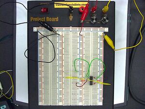
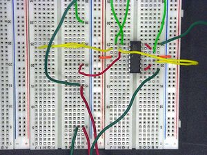
[[File:TwoBufferAndCopiesFull.jpg|thumb|Wide view of PBB 272 with LM 324 attached.]] | [[File:TwoBufferAndCopiesFull.jpg|thumb|Wide view of PBB 272 with LM 324 attached.]] | ||
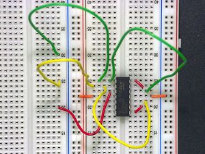
[[Image:TwoBufferAndCopies.jpg|thumb|Closeup of the LM 342 with buffer wiring on the right and and OpAmp 1 copy wiring on the left.]] | [[Image:TwoBufferAndCopies.jpg|thumb|Closeup of the LM 342 with buffer wiring on the right and and OpAmp 1 copy wiring on the left.]] | ||
| Line 18: | Line 18: | ||
<br clear=all> | <br clear=all> | ||
| − | ==== Through Section | + | ==== Through Section 6.3.4 ==== |
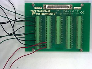
[[File:OpAmpCBWiring.jpg|thumb|CB-68LP connections showing four analog input measurements (green/black pairs), two analog outputs (red), and both AI and AO grounds.]] | [[File:OpAmpCBWiring.jpg|thumb|CB-68LP connections showing four analog input measurements (green/black pairs), two analog outputs (red), and both AI and AO grounds.]] | ||
Revision as of 22:19, 18 March 2013
The following page provides some supplemental information for the Operational Amplifiers lab for EGR 224L. It has been updated to Spring, 2013.
Contents
Changes
- None yet!
Troubleshooting
- Nothing here yet!
Images
Wiring
Through Section 6.3.3
This part involves wiring the three operational amplifiers used for this experiment. Note that amplifier "2" - which is on the bottom right of the chip in the pictures - is not used for this lab.
Click on the pictures at right to make them larger.
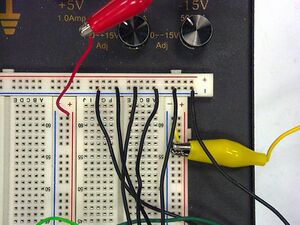
Through Section 6.3.4
This part involves wiring the measurement lines from the DAQ card through the CB-68LP to the PBB 272.
Click on the pictures at right to make them larger.
