Difference between revisions of "CB-68LP Pinout"
| Line 1: | Line 1: | ||
| + | [[Image:CB68LP.jpg|thumb|NI CB-68LP]] | ||
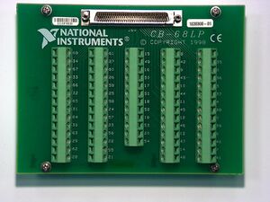
The National Instruments CB-68LP connection block allows for simple connections to NI data acquisition cards through a ribbon cable. The CB-68LP in particular has screw-operated window connections that allow for quick connections to wires. | The National Instruments CB-68LP connection block allows for simple connections to NI data acquisition cards through a ribbon cable. The CB-68LP in particular has screw-operated window connections that allow for quick connections to wires. | ||
Revision as of 22:39, 29 January 2009
The National Instruments CB-68LP connection block allows for simple connections to NI data acquisition cards through a ribbon cable. The CB-68LP in particular has screw-operated window connections that allow for quick connections to wires.
Mapping
The following chart lists the different connections as laid out on the National Instruments CB-68LP connection block when used in conjunction with the National Instruments PCI 6014e Data Acquisition Card. The list under the table describes the most commonly used channels.
| 68 ACH0 | 61 ACH12 | 15 DGND | 08 +5V | 01 FREQ_OUT |
| 34 ACH8 | 27 AIGND | 49 DIO2 | 42 GPCTR1_SRC | 35 DGND |
| 67 AIGND | 60 ACH5 | 16 DIO6 | 9 DGND | 2 GPCTR0_OUT |
| 33 ACH1 | 26 ACH13 | 50 DGND | 43 CONVERT | 36 DGND |
| 66 ACH 9 | 59 AIGND | 17 DIO1 | 10 TRIG2 | 3 GPCTR0_GATE |
| 32 AIGND | 25 ACH6 | 51 DIO5 | 44 DGND | 37 GPCTR0_SRC |
| 65 ACH2 | 58 ACH14 | 18 DGND | 11 TRIG1 | 4 DGND |
| 31 ACH10 | 24 AIGND | 52 DIO0 | 45 EXTSTROBE | 38 STARTSCAN |
| 64 AIGND | 57 ACH7 | 19 DIO4 | 12 DGND | 5 WFTRIG |
| 30 ACH3 | 23 ACH15 | 53 DGND | 46 SCANCLK | 39 DGND |
| 63 ACH11 | 56 AIGND | 20 RESERVED | 13 DGND | 6 UPDATE |
| 29 AIGND | 22 DAC0OUT | 54 AOGND | 47 DIO3 | 40 GPCTR1_OUT |
| 62 AISENSE | 55 AOGND | NA NA | 14 +5V | 7 DGND |
| 28 ACH4 | 21 DAC1OUT | NA NA | 48 DIO7 | 41 GPCTR1_GATE |
The most commonly used channels are:
- ACH# - analog input channel number #
- DAC#OUT - analog output channel number #
- DIO# - digital input/output (I/O) channel number #
- AIGND - ground (0 V) for the analog input channels
- AOGND - ground (0 V) for the analog output channels
- DGND - ground (0 V) for the digital I/O channels
Differential Channels
When the DAQ card is reading voltages in differential mode, two voltage measurements are required to actually measure a voltage difference. For the CB-68LP in conjunction with the PCI 6014e card, each differential input channel uses two lines - the line that is the same number as the channel is the + terminal and the line that is 8 higher than the channel is the - terminal. For example, taking a voltage on differential channel 4 would mean calculating the voltage difference between ACH4 on Line 28 and ACH12 on Line 61. The chart below shows the same map as above, but is labeled in terms of the positive and negative channels for differential mode:
| 68 Channel 0 + | 61 Channel 4 - | 15 DGND | 08 +5V | 01 FREQ_OUT |
| 34 Channel 0 - | 27 AIGND | 49 DIO2 | 42 GPCTR1_SRC | 35 DGND |
| 67 AIGND | 60 Channel 5 + | 16 DIO6 | 9 DGND | 2 GPCTR0_OUT |
| 33 Channel 1 + | 26 Channel 5 - | 50 DGND | 43 CONVERT | 36 DGND |
| 66 Channel 1 - | 59 AIGND | 17 DIO1 | 10 TRIG2 | 3 GPCTR0_GATE |
| 32 AIGND | 25 Channel 6 + | 51 DIO5 | 44 DGND | 37 GPCTR0_SRC |
| 65 Channel 2 + | 58 Channel 6 - | 18 DGND | 11 TRIG1 | 4 DGND |
| 31 Channel 2 - | 24 AIGND | 52 DIO0 | 45 EXTSTROBE | 38 STARTSCAN |
| 64 AIGND | 57 Channel 7 + | 19 DIO4 | 12 DGND | 5 WFTRIG |
| 30 Channel 3 + | 23 Channel 7 - | 53 DGND | 46 SCANCLK | 39 DGND |
| 63 Channel 3 - | 56 AIGND | 20 RESERVED | 13 DGND | 6 UPDATE |
| 29 AIGND | 22 DAC0OUT | 54 AOGND | 47 DIO3 | 40 GPCTR1_OUT |
| 62 AISENSE | 55 AOGND | NA NA | 14 +5V | 7 DGND |
| 28 Channel 4 + | 21 DAC1OUT | NA NA | 48 DIO7 | 41 GPCTR1_GATE |
Notice that, for the most part, pairs are right next to each other. The one exception is where Channel 4 is split between the first and second columns.
