Difference between revisions of "ECE 110/Equipment/Keysight 34460A"
(→References) |
|||
| Line 5: | Line 5: | ||
{{LaTeX Shortcuts}} | {{LaTeX Shortcuts}} | ||
== Measurements == | == Measurements == | ||
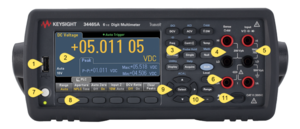
| − | [[File:ECE110 Keysight3446XA front.PNG|thumb|From [https://www.keysight.com/us/en/assets/9018-03876/service-manuals/9018-03876.pdf 34460A Series Operating and Service Guide], p. 24. Note that the 34465A is actually shown; the | + | [[File:ECE110 Keysight3446XA front.PNG|thumb|From [https://www.keysight.com/us/en/assets/9018-03876/service-manuals/9018-03876.pdf 34460A Series Operating and Service Guide], p. 24. Note that the 34465A is actually shown; the 34460A does not have the bottom left red terminal shown in the picture.]] |
The 34460A is capable of measuring resistance, voltage, current, capacitance, and temperature. If you examine the two rows of buttons slightly left of center at the top of the device, you will find the primary functions in white | The 34460A is capable of measuring resistance, voltage, current, capacitance, and temperature. If you examine the two rows of buttons slightly left of center at the top of the device, you will find the primary functions in white | ||
* DCV for DC Voltage. For a time-varying signal, this will be the overage value of the signal over a particular window of time, $$\bar{v}$$ | * DCV for DC Voltage. For a time-varying signal, this will be the overage value of the signal over a particular window of time, $$\bar{v}$$ | ||
Latest revision as of 14:44, 7 February 2024
Contents
Introduction
The digital multimeter will be used to measure resistances, voltages, currents, and temperatures. This document relates specifically to the 34460A Digital Multimeter from Keysight.
$$\newcommand{E}[2]{#1_{\mathrm{#2}}}$$
Measurements

The 34460A is capable of measuring resistance, voltage, current, capacitance, and temperature. If you examine the two rows of buttons slightly left of center at the top of the device, you will find the primary functions in white
- DCV for DC Voltage. For a time-varying signal, this will be the overage value of the signal over a particular window of time, $$\bar{v}$$
- ACV for AC Voltage. This will be the RMS (root-mean-squared value) of the signal's deviation from its own average; that is,$$\E{V}{RMS,AC}=\sqrt{\frac{1}{T}\int_T(v(\tau)-\bar{v})^2}\,d\tau$$. Note that $$\E{V}{RMS}^2=\E{V}{RMS,AC}^2+\bar{v}^2$$; this will be useful for comparing full-RMS calculations with the component parts found by the multimeter.
- $$\Omega$$2W for 2-wire resistance measurements
- Freq for measuring the frequency of an AC voltage. You can also choose to measure the period in this mode.
- Cont for a continuity beeper to check for a short circuit, and
- Temp for a temperature reading
There are also alternate functions in Blue
- DCI for DC current
- ACI for AC current
- $$\Omega$$4W for a more accurate 4-wire resistance measurement
- A capacitor symbol for measuring capacitance, and
- A diode symbol for checking diode direction.
To access the alternative functions, first press the blue shift button.
Note that the wiring is different for different types of measurement. There are five banana jack connectors on the multimeter located on the right side of the front panel. The purpose for each is indicated by the small print above the jack.
- For voltage measurements, use the top right red terminal for the + node and the middle right black terminal for the - node
- For current measurements, use the bottom red terminal and the middle black terminal. The current will be measured as it flows from the red terminal to the black terminal through the meter.
- For a 2-wire (2W) resistance measurement, use the top right red terminal and the middle right black terminal.
- For more accurate 4-wire (4W) resistance measurements, use bot top red terminals attached to one side of the resistor and both middle black terminals attached to the other side.
- To test continuity (i.e. to see if there a short circuit) or diode directionality, use the top right red terminal and the middle right black terminal.
Note
- As a voltmeter, the multimeter has very high - but not infinite - resistance. (An ideal voltmeter has infinite resistance)
- As an ammeter, the multimeter has very small - but not zero - resistance. (An ideal ammeter has zero resistance)
References
- 34460A product page from Keysight
- 34460A Series Operating and Service Guide from Keysight
- 34460A Series Data Sheet from Keysight